Build Your Own IoT System with SwitchLink

Step-by-Step Guide

1. Introduction

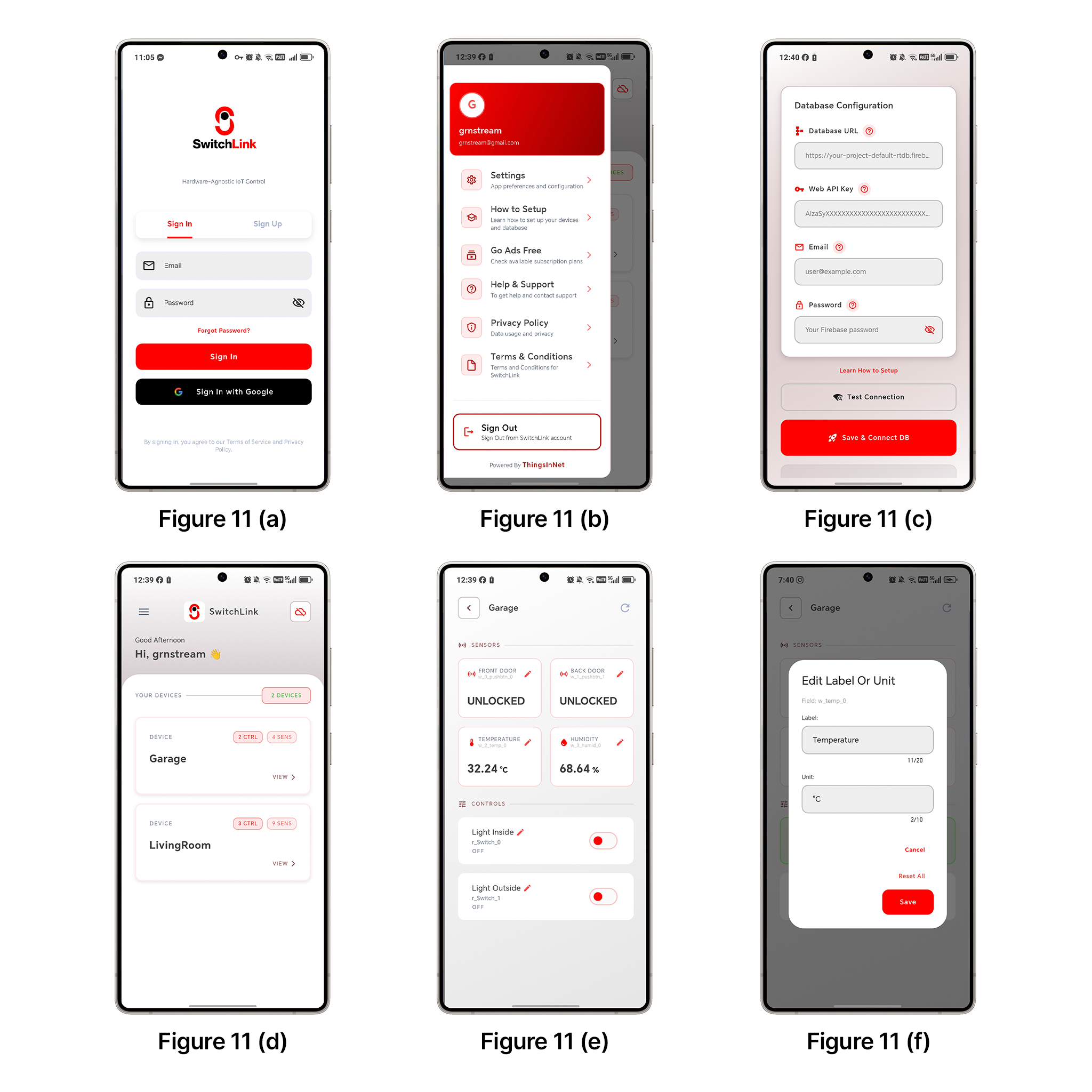
SwitchLink lets you connect, monitor, and control your own customized IoT devices directly from your smartphone. It works as a flexible mobile dashboard that communicates with your cloud database in real time, giving you full control over your devices and your data.

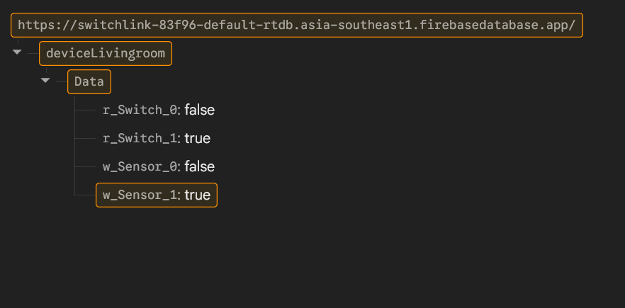
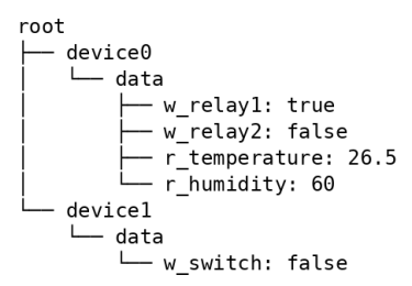
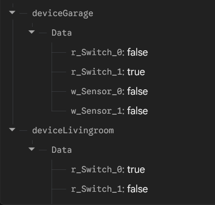
Unlike many IoT platforms that depend on proprietary servers, SwitchLink is built around a user-owned architecture. Your devices connect directly to your Firebase Realtime Database, while the mobile app reads and writes data to the same database. This allows you to build scalable IoT systems without relying on centralized vendor specific platforms.

The app automatically detects compatible devices and generates a control interface based on the structure of your database. This means you can add new devices without redesigning the mobile interface.

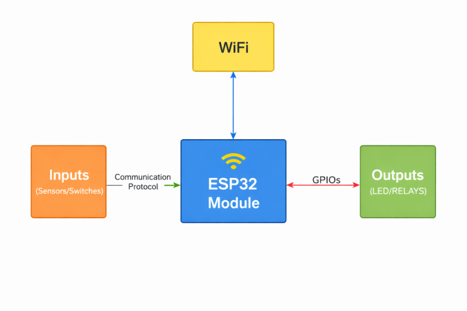
This manual explains a simple, flexible IoT setup that works with almost any microcontroller (ESP32, ESP8266, Raspberry Pi, STM32, etc.) as long as it can connect to the Internet and read/write data.

With this framework:

  • Your IoT device connects directly to your Firebase Realtime Database.
  • The SwitchLink mobile app becomes your ready-made dashboard to monitor sensors and control appliances.
  • You retain full ownership of your device and your data (no central server, no proprietary cloud in the middle).

1.1 How it works (in one idea)

  • Your device reads sensors and updates Firebase in real time.
  • The SwitchLink app reads the same Firebase paths and sends control commands back.
  • The app automatically adapts to your device based on a simple naming/structure convention defined by SwitchLink.

1.2 What you will learn in this manual

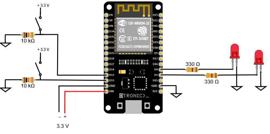
  1. Set up the hardware (ESP32 is used as an example)
  2. Create and configure a Firebase Realtime Database
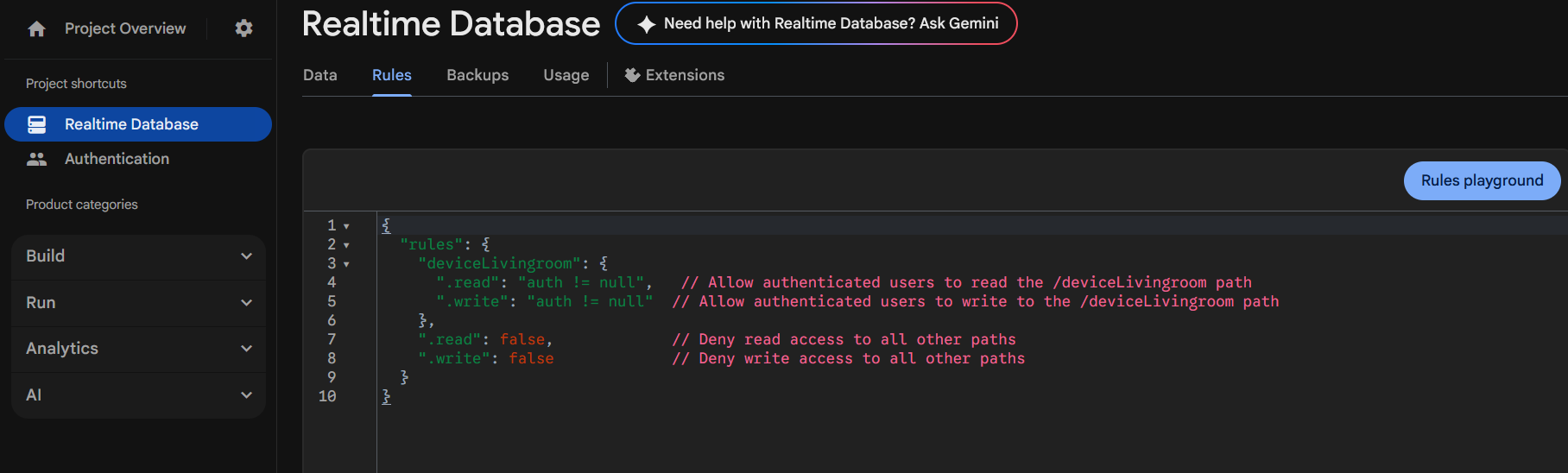
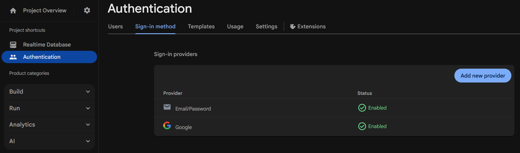
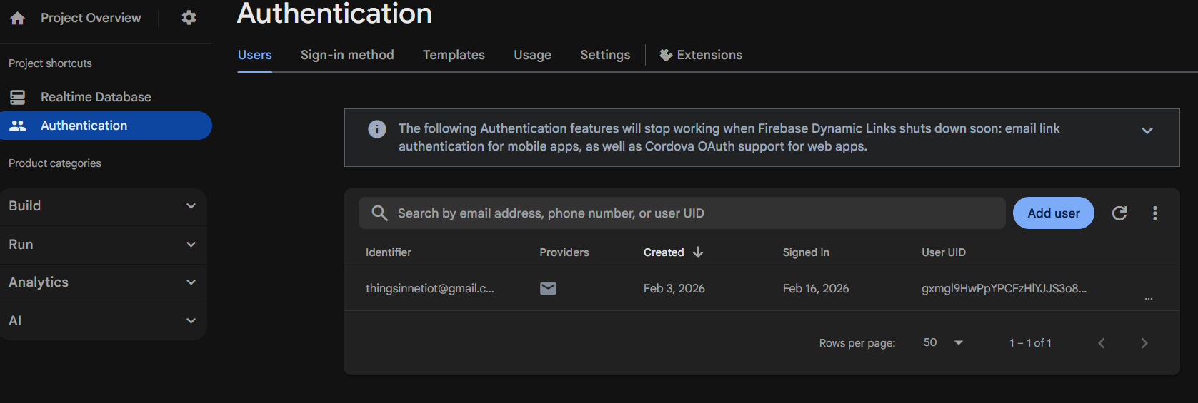
  3. Enable authentication and define the correct database structure for devices
  4. Update and upload the demo firmware
  5. Connect the SwitchLink app to your Firebase project
  6. Monitor sensor values and control outputs in real time

1.3 After completing this guide, you will have

  • A device that securely connects to the cloud
  • Control buttons in the app that work instantly
  • Sensor values that update live
  • A mobile app that detects your device automatically (no hardcoding UI per device)

1.4 Where can you use it?

You can use it in a wide range of applications, including home automation, smart farming, research prototypes, industrial control systems, and scalable IoT deployments.

1.5 Hardware note

You can use any compatible IoT chip for your project. The only requirement is that your firmware follows the database naming and structure conventions when reading and writing data in Firebase. In this manual, we use the ESP32 because it is affordable, widely used, and well supported.

2. ESP32 Hardware & Demo Firmware Setup

2.1 Hardware Requirements for the Demo

The firmware is compatible with most ESP32 boards, including:

  • ESP32 Dev Module
  • ESP32 DevKit V1
  • ESP32-WROOM-32 based custom boards

Minimum requirements:

  • ESP32 with Wi‑Fi support
  • USB cable for programming
  • Arduino IDE (latest)

Optional (for demo control):

  • LEDs
  • Relays
  • Push buttons
Block diagram of the IoT unit
Figure 1: Block diagram of the IoT unit

Figure 1 illustrates the overall architecture of the proposed IoT unit, highlighting how sensors and switches (inputs) and actuators such as LEDs or relays (outputs) are integrated through the ESP32 module with WiFi connectivity.

The ESP32 acts as the central controller, receiving data from sensors via supported communication protocols and controlling external devices through its GPIO pins. Any output-capable GPIO can be used to drive relays or other appliances, while various standard communication protocols may be used to interface with sensors and input devices. Users should always refer to the specific ESP32 module datasheet to verify GPIO capabilities and hardware limitations.

A simple wiring diagram is provided below to help you get started with the supplied demo firmware.

Demonstration wiring diagram
Figure 2: A simple wiring diagram or circuit matches the firmware provided

Figure 2 shows a simple demonstration wiring diagram that matches the provided firmware setup. In this example, GPIO12 and GPIO13 are connected to two switches using 10 kΩ pull-down resistors. These inputs can be replaced with any compatible sensors of your choice (e.g., digital sensors or signal outputs), as long as you update the corresponding GPIO mappings and logic in the firmware.

For output control, the circuit uses two LEDs with 330 Ω current-limiting resistors as indicators. To control an external electrical load (such as a pump, light, or fan), replace the LEDs and resistors with a suitable relay module (or driver circuit) and connect it to an output-capable GPIO as defined in the firmware.

An example relay module circuit is shown in Figure 3. You may build your own relay module using the schematic shown in Figure 4 or use any compatible relay module available on the market to switch and control external electrical loads.

Relay module circuit example
Figure 3: Example relay module
Relay module schematic
Figure 4: Relay module schematic for you to build if required

VIN5 (5V Input): The “VIN5” pin must be supplied with a stable 5V power source. This 5V supply powers the relay coil and the driver circuit. Without this 5V input, the relay will not operate.

OUT_0 (Control Signal): The “OUT_0” pin should be connected directly to the selected digital output GPIO pin of the ESP32. This GPIO pin sends the control signal (HIGH or LOW) to activate or deactivate the relay through the driver circuit.

In sample terms:

  • VIN5 = Power for the relay (5V)
  • OUT_0 = Control signal from ESP32
⚠ Electrical Safety Notice:

When switching external electrical loads (especially AC mains voltage), ensure proper insulation, secure wiring, and adequate isolation between low-voltage and high-voltage circuits. Always disconnect the power supply before making wiring changes. If you are not experienced in handling high-voltage systems, consult a qualified electrician. Improper wiring may result in electric shock, equipment damage, or fire.

2.2 Required Software

  1. Arduino IDE (latest version)
  2. ESP32 board support installed in Arduino IDE (https://randomnerdtutorials.com/installing-the-esp32-board-in-arduino-ide-windows-instructions/)
  3. Required libraries:
    • FirebaseClient by Mobitz
    • WiFi

2.3 Firmware Configuration

After completing the hardware construction of your IoT device, download the sample firmware provided here(switchlink_usecase_one) and apply the necessary modifications as described below.

Prerequisites

  • To fill in the Firebase Realtime Database related parameters, please complete the steps in Section 3 of this manual.

In the demo firmware, the following values must be configured:

#define WIFI_SSID "YourWiFiName"

#define WIFI_PASSWORD "YourWiFiPassword"

#define FIREBASE_API_KEY "YourFirebaseAPIKey"

#define FIREBASE_DATABASE_URL "https://your-project-id-default-rtdb.region.firebasedatabase.app/"

#define FIREBASE_USER_EMAIL "user@email.com"

#define FIREBASE_USER_PASSWORD "password"

#define DEVICE_NAME "deviceLivingroom"

Important notes

  • DEVICE_NAME determines the device ,root node namein the database.
  • Changing DEVICE_NAME creates a new device entry in Firebase.
  • The firmware reads and writes data under:
    • DEVICE_NAME/data/

2.4 Demo Firmware Behavior

This section explains how the demo firmware operates after being uploaded to the ESP32, including startup and data synchronization with Firebase.

  • On boot, the ESP32 connects to Wi‑Fi
  • It authenticates with Firebase using email/password
  • It creates the device path if it does not exist
  • It continuously syncs data under:
    • DEVICE_NAME/data/

Behavior by variable type

  • Write-only fields (w_)
    • Written by the ESP32, and read by the mobile app
    • Used for sensor data such as temperature, humidity, motion state, etc.
  • Read-only fields (r_)
    • Written by the mobile app, and read by the ESP32
    • Used for relays, LEDs, switches, etc.
Realtime Database showing live device data
Figure 5: Firebase Realtime Database displaying live device data and real-time sensor/status updates
Note:

If you want to try a more advanced use case, please use code provided here. Make sure to follow the hardware setup instructions given in the code before uploading the firmware to the ESP32 chip.


3. Setting Up a Firebase Realtime Database

3.1 Create a Firebase Project

  1. Go to https://console.firebase.google.com/
  2. Click Add project
  3. Enter a project name (any name is fine)
  4. Disable Google Analytics (optional)
  5. Click Create project

Once the project is created, you will be taken to the Firebase console.

3.2 Create a Realtime Database

  1. In the left sidebar, click Build → Realtime Database
  2. Click Create Database
  3. Choose a database location (pick the closest region)
  4. Select Start in test mode (recommended for getting started)
  5. Click Enable

Your database URL will look like:
https://your-project-id-default-rtdb.region.firebasedatabase.app/
Your API key will look like:
AIza××××××××××××××××××××××××××
Save this URL and API key: They will be required by both the ESP32 firmware and the mobile app.

To find the database URL, open your project and navigate to the “Build” → “Realtime Database” section. Once inside, look at the top of the database page and you’ll see the database URL displayed (it usually looks something like https://your-project-id-default-rtdb.region.firebasedatabase.app/).

Alternatively, you can also find it in Project settings → General → Your apps, where it appears in the Firebase configuration snippet as databaseURL (for web apps).

To find the API key, go to the Firebase Console and select your project. From there, click the gear icon (⚙️) next toProject Overview and open Project settings.

In the General tab, scroll down to the “Your apps” section and select the web app create one if you haven’t already.(add app > Select a platform to get started : select web) You will see a Firebase configuration snippet that includes the apiKey (it usually looks like AIza××××××××××××××××××××××××××××××).

⚠️ Important:

Test mode allows open access for a limited time. Before deploying or sharing your project, configure Realtime Database Rules to restrict access. For more information, see Figure 6.

You can find the rules editor here:
Firebase Console → Build → Realtime Database → Rules

Realtime Database Rules editor screenshot
Figure 6: Firebase Realtime Database Rules editor showing access control configuration for device paths.

3.3 Configure Authentication

The mobile app and ESP32 firmware authenticate users before accessing the database.

In Firebase Console:

  1. Go to Build → Authentication
  2. Click Get started
  3. Enable Email/Password authentication
  4. Save the changes

Then create at least one test user:

  1. Open the Users tab
  2. Click Add user
  3. Enter an email and password
Firebase Authentication sign-in method (Email/Password)
Figure 7: Firebase Authentication console showing Email/Password sign-in method
Firebase Authentication Users tab
Figure 8: Firebase Authentication Users tab displaying registered user accounts

3.4 Database Structure

Each ESP32 device, once powered on, automatically creates its own node at the root level of the Firebase Realtime Database using the device name defined in the firmware. This structure allows multiple devices to operate independently while sharing the same database.

Example structure:

Realtime Database root view displaying multiple device nodes with individual data paths
Figure 9: Firebase Realtime Database root view displaying multiple device nodes with individual data paths.
Multiple device nodes in Firebase
Figure 10: Firebase Realtime Database root view.

Figure 10 shows multiple device nodes automatically created once the devices are powered on (e.g., deviceGarage and deviceLivingroom), each with its own Data path containing live status values.

Notes:

  • The device name must be unique: All control and sensor variables are stored under deviceName/data/
  • Variables are differentiated by a prefix:
    • w_ → writable (controls, switches)
    • r_ → read-only (sensor data)

This naming convention allows the SwitchLink mobile app to automatically decide how to display each field.

4. Testing the Device and Firebase Communication Flow

After completing the hardware setup, firmware configuration, and Firebase setup, follow these simple steps to verify proper communication between the ESP32 and Firebase:

  1. Upload the Firmware

    Upload the configured demo firmware to the ESP32 using the Arduino IDE. To complete the task, follow the instructions in Section 2 and Section 3 if you have not done so yet.

  2. Open Serial Monitor

    Set the baud rate as defined in the firmware (commonly 115200).

    Confirm:

    • Wi-Fi connection successful
  3. Check Firebase Console

    Go to:

    Firebase Console → Build → Realtime Database → Data

    Verify that:

    • A new root node with your DEVICE_NAME appears
    • The data/ node is created
    • r_ variables are updating automatically
  4. Test Writable Variables
    • Manually change a w_ variable (e.g., w_relay1) in Firebase
    • Observe the ESP32 response (LED or relay switching)

If both r_ updates (ESP32 → Firebase) and w_ control responses (Firebase → ESP32) work correctly, the device–cloud communication is successfully established.

The next step is even more interesting:

You can download the SwitchLink app from the Play Store, configure the settings as explained in Section 5, and start monitoring and controlling your device.

Get SwitchLink on Google Play

5. Connecting the Mobile App to Firebase

Mobile app overview screenshots
Figure 11: Mobile app overview screenshots (credentials, device list, device data, value edit)

5.1 Download the mobile app and signup

Download the SwitchLink mobile app from the Play Store and sign up.

The app will request the following details to connect to your Firebase Realtime Database (created in Section 3 of this document).

5.2 Firebase Credentials Required

When opening the app for the first time, the user must provide the following details (Figure 11(c)):

  • Firebase API Key
  • Firebase Database URL
  • Firebase Email (Firebase user email)
  • Firebase Password (Firebase user password)

You can find the above credentials in Sections 3.1, 3.2, and 3.3. These credentials are used only to authenticate and access the user’s own Firebase project.

5.3 Connecting to Firebase

  1. Open the mobile app
  2. Login for connecting to your firebase account

If authentication is successful:

  • The app connects to the Realtime Database
  • Root-level nodes are scanned for available devices

5.4 Device Discovery

The app automatically lists all devices found at the database root:

/deviceWarehouse /deviceLivingRoom

Each entry corresponds to a device name defined in ESP32 firmware.

5.5 Device Control & Monitoring Screen

When the user taps a device in the interface shown in Figure 11(d):

  • The app opens deviceName/data/.
  • Each field is analyzed by its prefix.

Display rules used by the app:

  • Fields starting with w_ are shown as interactive controls(switches, toggles)
  • Fields starting with r_ are shown as read-only indicators(labels, cards)

Examples:

  • w_relay1 → Toggle switch
  • r_temperature → Numeric display
  • r_humidity → Percentage display

The device-related data are shown in Figure 11(e). Users can assign a unique name and unit to each value using the interface in Figure 11(f), which opens with a long tap on the value.

6. Troubleshooting

Device Does Not Appear in the App

  • Confirm the ESP32 is connected to Wi-Fi
  • Verify DEVICE_NAME is set and unique
  • Check that data exists under: /deviceName/data/

Authentication Errors

  • Double-check email and password in firmware and app
  • Ensure Email/Password auth is enabled in Firebase
  • Verify the API key matches the correct Firebase project

Data Not Updating in Real Time

  • Confirm the ESP32 is still connected to Wi-Fi
  • Check Firebase console for live value changes
  • Make sure variable names follow the w_ / r_ prefix convention

Switch Toggles but Hardware Does Not Respond

  • Confirm firmware is listening to the correct database path
  • Ensure writable variables start with w_
  • Verify GPIO assignments in firmware

Summary

  • Users bring their own ESP32 hardware
  • Users create their own Firebase project
  • Device identity is controlled by a simple firmware constant
  • Sensor data and control data share a unified structure
  • Naming conventions allows the mobile app to automatically adapt

This architecture keeps the system flexible, scalable, and hardware-agnostic.